Note: That info is used as a complimentary information for certified professionals
Pre-Installation: Safety & Installation Guide
1. Professional Installers Only
It is recommended that the equipment be installed by trained electricians or certified technicians.
2. Before You Start
3. Choosing the Right Location
Install the equipment in a dry, cool area (avoid high humidity or excessively hot spots).
Maintain proper spacing between inverters to ensure adequate ventilation.
4. Use High-Quality Parts (Important!)
Using cheap or low-quality DC/AC components (such as breakers or wires) can lead to:
Malfunctioning: Breakers may fail to trip when necessary.
Power Imbalance: Higher resistance can result in uneven power distribution.
Overheating: This can cause component failure or even fire.
System Failure: A single faulty component can compromise the entire system.
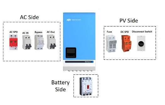
Electrical protection devices
*Fuses protect against short circuits,
Photovoltaic and Battery Fuses
1. Fuse Ratings
Fuse Placement & Selection
1. Location
2. Fuse Type & Ratings
3. Recommended Brands
The following brands have undergone rigorous testing and meet required certifications:
ABB
Schneider Electric
Nader
Zbeny
Chint
Isolators and disconnectors:
Role of Isolators (Disconnect Switches):
Isolators, also known as disconnect switches, they are engineered to suppress arcing to safely disconnect the Photovoltaic during maintenance.
Role of Disconnectors between the batteries and inverters:
Disconnectors (or disconnect switches) are used to isolate specific components, such as inverters from batteries, for maintenance or safety purposes.
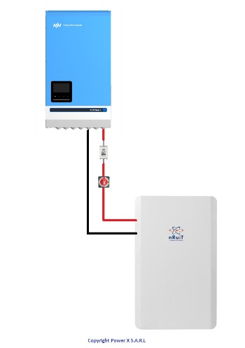
Use high-quality copper conductors to minimize resistance and ensure safety. Low-quality cables often contain impure alloys or substandard materials, increasing resistance and posing risks such as overheating or energy loss.
Cables:
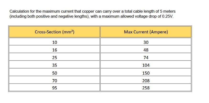
Refer to this table for the battery, DC copper cable thickness:

General calculation for Dc cables connecting the battery and inverter, where the allowable Dc voltage drop is less than 0.3V
For a cable less than 5m (Total length including positive and negative):
Cable Sizing Guide
1. Standard Cable Sizing
2. For Cables Less Than 10m
Voltage Drop & Cable Considerations
1. Maximum Allowable Voltage Drop
Limit: ≤2.5% of the system voltage.
Example: For a 48V battery system, the maximum voltage drop is:
48V×0.025=1.2V48V \times 0.025 = 1.2V48V×0.025=1.2V
2. Consequences of Excessive Voltage Drop
Reduced Efficiency: Power loss manifests as heat.
Overheating Cables: Increases the risk of fire.
System Instability: May cause inverter shutdowns or battery damage.
3. Resistance & Energy Distribution
Battery and Inverter Wiring Guidelines:
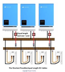
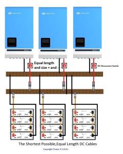
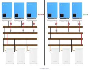
To ensure the maximum balance in charging and discharging between batteries from one side, and the closest possible inverters balance in charging and discharging from the other side (in parallel system):
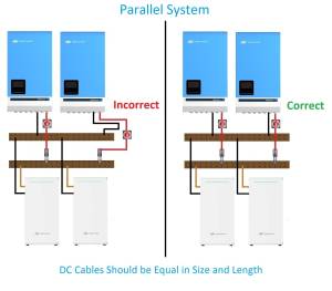
- Equal Cable Lengths: In parallel systems, ensure identical cable lengths between inverters and batteries to prevent imbalances in current distribution.
- Uniform cables, of the same brand, alloy, and specifications to maintain consistent electrical characteristics (e.g., resistance, conductivity).
- Uniform Components: same brand and specs MCB, MCCB, fuses or disconnectors in a system (Ensuring the nearest possible conductivity).
- Optimized Busbar Connections:
- Keep busbar connections as short as possible to minimize resistance and voltage drop.
- Maintain equal distances between all connectors to ensure balanced energy distribution between batteries and inverters.
Purpose: These practices reduce resistance imbalances between inverters charge/discharge (in parallel) also minimize uneven charging and discharging between battery packs, enhancing energy efficiency, and mitigate risks of overheating or uneven load sharing in parallel configurations.
In parallel system, it is mandatory that dc cables will be exact in cable length and size, and preferably taken from the same point, as resistance on wires will be close as much as possible between both inverters.
AC Wiring for Parallel Inverters – Key Guidelines
To ensure balanced current sharing and optimal system performance, follow these best practices:
1. Input Side (AC Breaker to Inverters)
2. Output Side (Inverters to Circuit Breaker)
3. Purpose & Benefits
General Best Practices
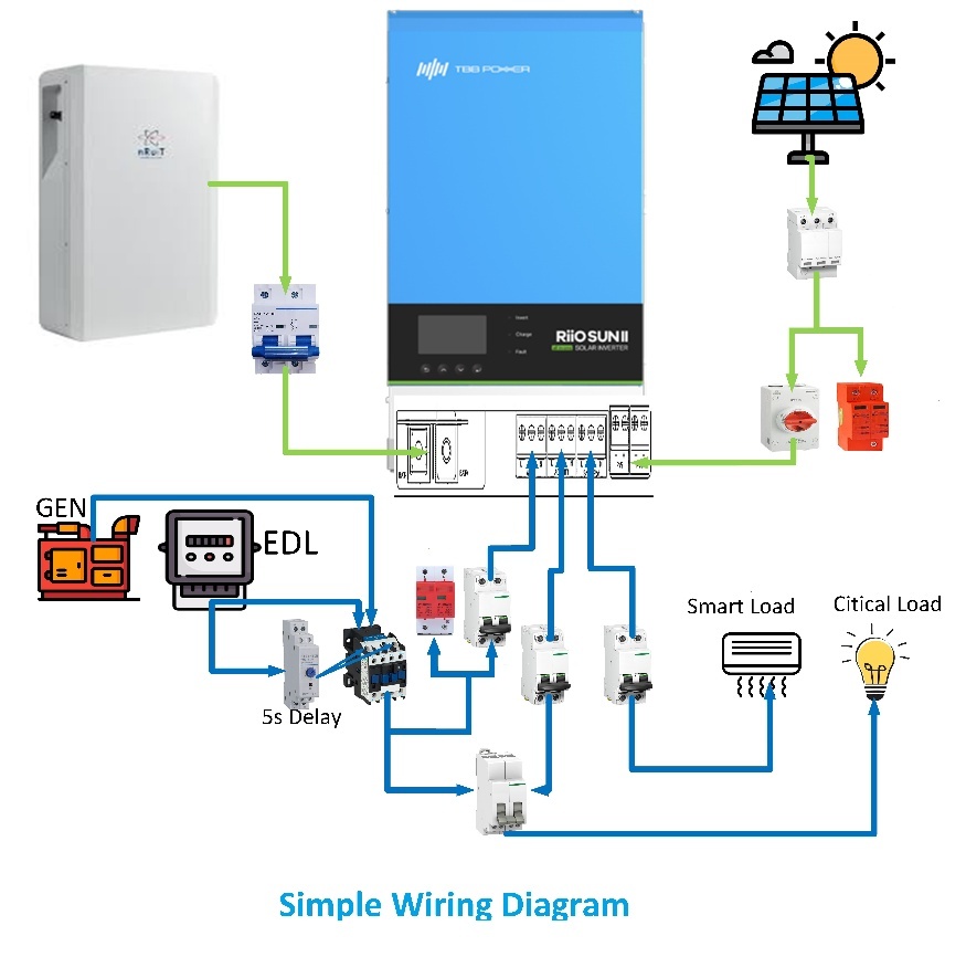
Keep your system as simple as possible. Add the necessary Protection components, And most importantly: High quality component.
Earthing documentation:
Refer to our earthing documentation.
Copyright: Power-X SARL Team